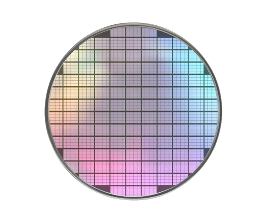
PEC Etching of Intrinsic Silicon
Porosifying intrinsic silicon for mid-infrared photonics by bonding a degenerately doped p++ carrier wafer to supply the free carriers the electrochemical etch needs.
Introduction & Motivation for Infrared Photonics
In short: silicon chips are great at handling near-infrared light, but nobody’s pushed them hard into the mid-infrared range where you can chemically “fingerprint” a gas or liquid. Porous silicon can get there — if you can actually etch it, which turns out to be the hard part for the specific wafers this thesis needed.
Most silicon photonics work targets near-infrared data links. The mid-infrared band gets far less attention, even though it’s the range spectrometers use for chemical detection. Silicon is a natural fit: cheap, and already integrated at scale.
Porous silicon is the key material here. Etch away part of the silicon and its refractive index becomes tunable anywhere from to , instead of bulk silicon’s fixed — enough range to build high-contrast optical structures in a single material.
The Intrinsic Silicon Porosification Challenge
In short: the silicon this thesis needed to etch barely conducts, and etching needs conductivity. So I had to give it some, artificially, without changing the material itself.
Porous silicon usually starts from doped wafers, because electrochemical etching consumes positive charge carriers (holes):
Intrinsic silicon (i-Si) has almost no free carriers of its own (), so it runs out of holes almost instantly and barely etches at all.
My fix: bond a heavily-doped carrier wafer onto the i-Si. Under light and a positive bias, holes diffuse out of the layer and into the i-Si — supplying, from the outside, the carriers the intrinsic silicon doesn’t have on its own.
Ohmic Contact Metallurgy & Sintering
In short: the bond between the two wafers needs a clean electrical path, or the etch would waste energy as heat instead of removing silicon.
I used a Ti/Al metal stack to connect the two wafers electrically. A poor contact here means voltage spikes and wasted heat during etching instead of clean current flow.
Annealing at makes the titanium react with the silicon underneath it, forming titanium silicide — a solid, low-resistance electrical weld between the metal and the wafer:
The leftover titanium isn’t wasted either: because forms more readily than ( vs. kcal/mol), any unreacted titanium mops up native oxide at the interface before it can get in the way.
Process Flow
The complete cleanroom fabrication flow developed for senior thesis work is outlined below:
[Degrease Wafers]
       │
       ▼
[O2 Descum (150W, 1 min)]
       │
       ▼
[1-min HF Dip (Native Oxide Removal)]
       │
       ▼
[E-Beam Deposition (25/400 nm Ti/Al)]
       │
       ▼
[Hand Cleave into Four Quarters]
       │
       ▼
[O2 Plasma Activation (0.4 mbar, 75-100W)]
       │
       ▼
[SUSS Vacuum Wafer Bonding (400 °C)]
       │
       ▼
[Post-Bond Anneal (400 °C, 30 mins)]